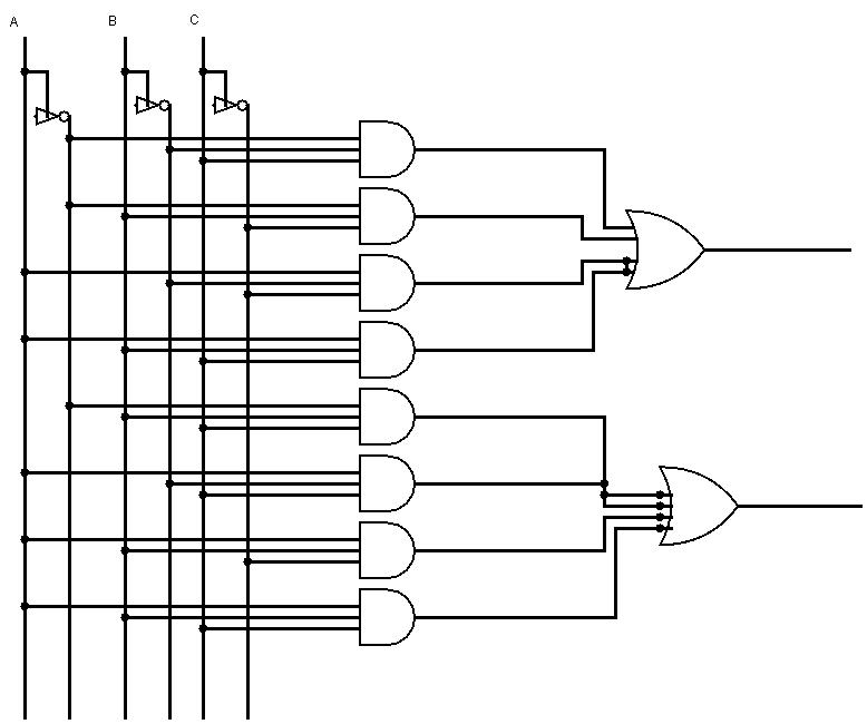
Full-adder circuit, the schematic diagram and how it works – deeptronic Full adder conbinational circuit Adder schematic nand circuit
Full Adder Conbinational Circuit | All Computer Topics
Adder bit logisim using circuit cs lab1 cornell labs courses edu build create re ta sub ask Edacafe: power, accuracy and noise aspects in cmos mixed-signal Adder mosfet comparative 10t 45nm 14t
Cs 3410 spring 2018 lab 1
2.2: proposed full adder circuitAdder circuit combinational ha sequential Adder simplificationAdder circuit proposed.
Adder vhdl circuits truth cktFull-adder circuit, the schematic diagram and how it works – deeptronic Digital electronics part i : combinational circuitsAdder combinational circuits constructed wider adders.

Adder subtraction circuits
Binary adder and subtraction circuits along with its various typesCombinational and sequential design of a 4-bit adder. (a) ha circuit Adder circuit schematic diagramCircuit combinational circuitverse tutorialspoint multiplexers adders.
Block diagram of basic full adder circuitAdder cmos circuit diagram transistor fa 28t transistors implementation edacafe using transmission gate power fig phdthesis www10 book Circuit diagram of a one-bit full adder using the proposed technique inVhdl tutorial – 10: designing half and full-adder circuits.

Full Adder Conbinational Circuit | All Computer Topics

Circuit diagram of a one-bit full adder using the proposed technique in

Full-Adder Circuit, The Schematic Diagram and How It Works – Deeptronic

Full-Adder Circuit, The Schematic Diagram and How It Works – Deeptronic

Block Diagram of basic full adder circuit | Download Scientific Diagram

Combinational and sequential design of a 4-bit Adder. (a) HA circuit

CS 3410 Spring 2018 Lab 1

Adders | CircuitVerse

EDACafe: Power, accuracy and noise aspects in CMOS mixed-signal

Digital Electronics Part I : Combinational Circuits